What is FDM 3D Printing?
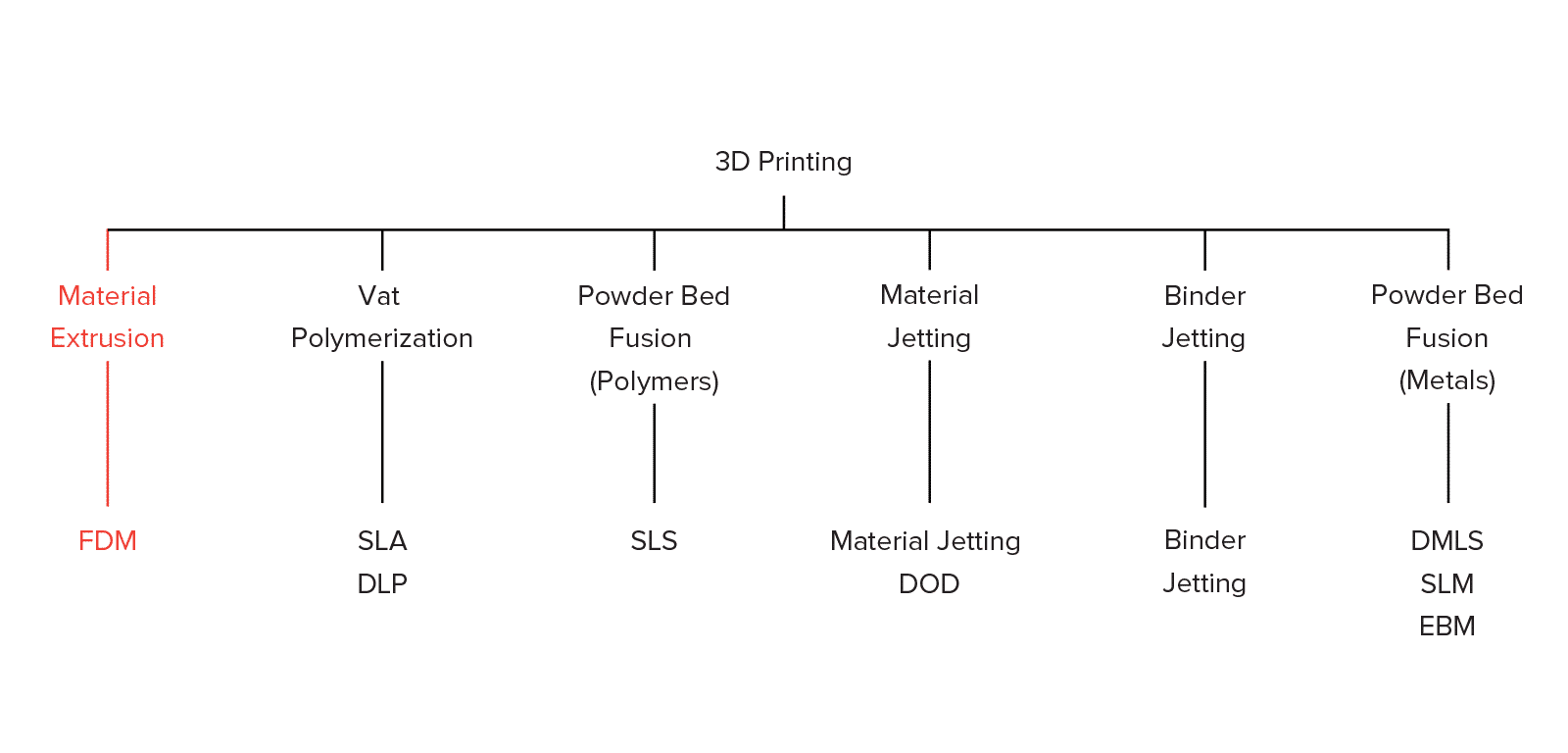
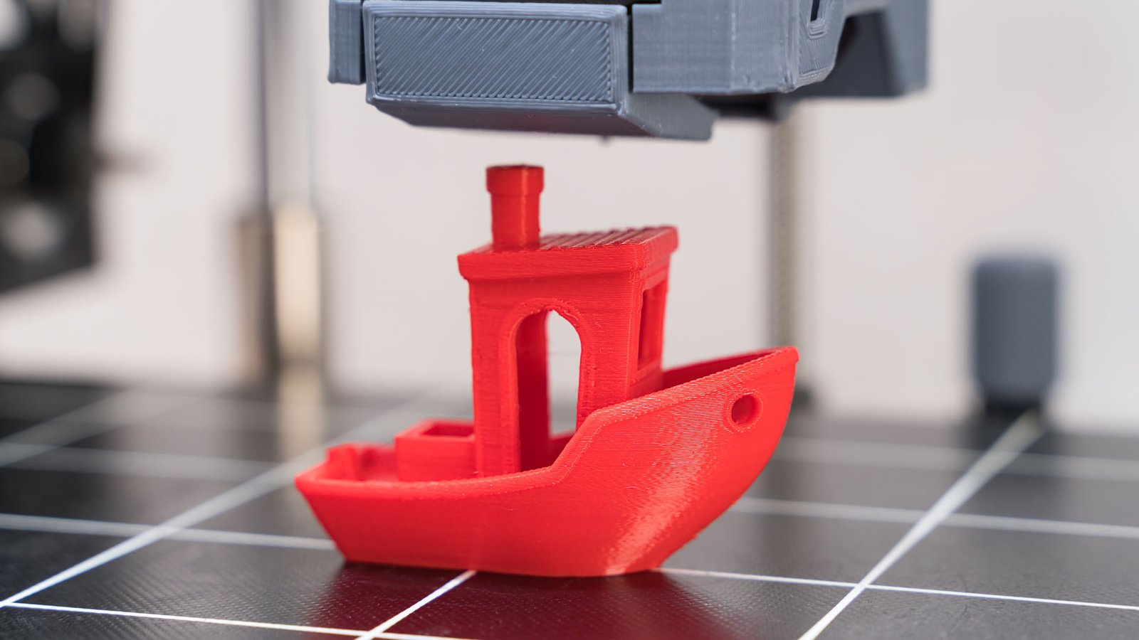
Fused Deposition Modeling (FDM), or Fused Filament Fabrication (FFF), is an additive manufacturing process that belongs to the material extrusion family. In FDM, an object is created layer by layer by depositing melted selected materials along a predetermined path. The materials used are thermoplastic polymers, produced in filament (string-like) form.
What is FDM?
FDM is the most widely used 3D printing technology and often the first technology that people are exposed to. In this article, the fundamental principles and key aspects of this technology are presented.
A designer, when making a part with FDM, must consider the capabilities and limitations of the technology, as this will help them achieve the best result.
How does FDM work?
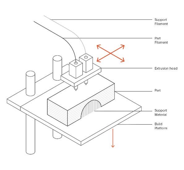
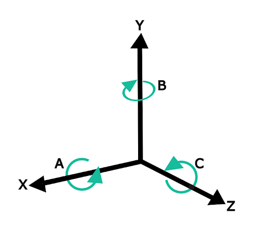
A spool of thermoplastic filament is first loaded into the 3D printer. When the nozzle reaches the desired temperature, the filament is fed to the extrusion head and into the nozzle, where it melts. The extrusion head is connected to a 3-axis system that allows it to move in the X, Y, and Z directions. The melted material is extruded in the form of thin strands and deposited layer by layer in predetermined places, where it cools and solidifies. Sometimes the cooling of the material is accelerated using cooling fans attached to the extrusion head. To fill an area, multiple passes are required (similar to coloring a rectangle with a marker). When one layer is completed, the bed of the 3D printer goes down (or in other machines, the extrusion head moves up) and a new layer is deposited. This process is repeated until the part is completed.
Main Features of FDM
Printer Parameters
Most FDM systems allow the adjustment of several process parameters, including nozzle and bed temperature, build speed, layer height, and cooling fan speed. These are generally set by the operator, so they shouldn’t be a major concern for the designer.
What is important from a designer’s perspective is the build size and layer height. The build size of parts in a typical desktop 3D printer is usually 200 × 200 × 200 mm, while for industrial machines it can be up to 1000 × 1000 × 1000 mm. If a desktop 3D printer is preferred (for example, to reduce costs), a large model can be divided into smaller parts and then assembled.
The typical layer height used in FDM varies between 50 to 400 microns and can be specified upon order. A smaller layer height produces smoother parts and records curved geometries with more accuracy, while a larger height produces 3D parts faster and at a lower cost. The most common layer height is 200 microns.
Warping in 3D printing
Warping is one of the most common defects in FDM. When extruded materials cool during solidification, their dimensions shrink. As different parts of the 3D print cool at different rates, the dimensions of the 3D print also change at varying rates. Cooling causes internal stresses that pull the underlying layer upwards, causing warping. Warping can be prevented with more precise temperature monitoring and by increasing the adhesion between the part and the bed of the 3D printer.
Designer decisions can also reduce the likelihood of warping:
- Large flat areas (imagine a rectangular box) are more prone to warping and should be avoided if possible.
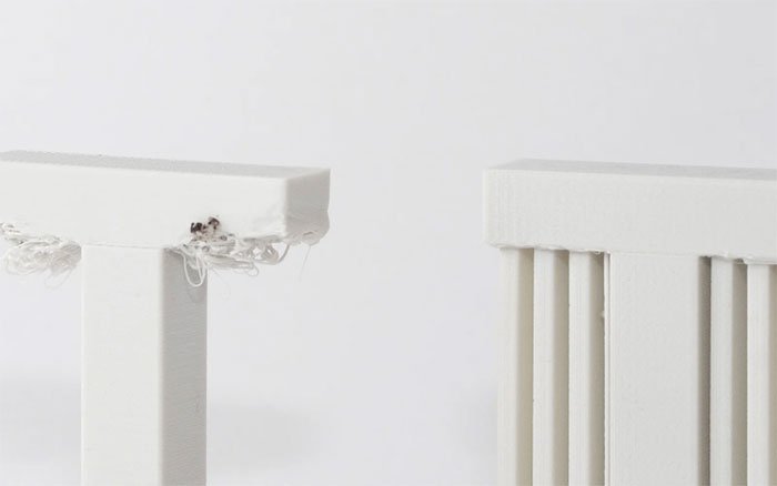
- Narrow protruding parts (think of the tines of a fork) are also prone to warping. In this case, adding some sacrificial material at the edge of the thin part (for example, a 200-micron thick rectangle) can increase the contact area with the build platform and prevent warping.
- Sharp corners warp more than rounded shapes, so adding fillets to the design is a good practice.
- Different materials are more prone to warping: ABS is more sensitive to warping due to its higher glass transition temperature and relatively high thermal expansion coefficient compared to PLA or PETG.
Layer Adhesion
Good adhesion between deposited layers is crucial for an FDM part. When the melted thermoplastic exits through the nozzle, it presses against the previous layer. The high temperature and pressure re-melt the surface of the previous layer, enabling the new layer to bond with the previously printed part.
The strength of the bond between different layers is always less than the base material’s strength.
This means that FDM parts are inherently anisotropic: their strength in the Z-axis is always less than their strength in the XY plane. Therefore, when designing parts for FDM, the orientation must be considered.
For example, tensile tests of horizontally printed parts in ABS with 50% infill compared with parts tested in the vertical direction showed nearly 4 times greater tensile strength in the X, Y printing direction compared to the Z direction (17 megapascals compared to 4.4 megapascals) and almost 10 times more elongation before breaking (4.8% compared to 0.5%).
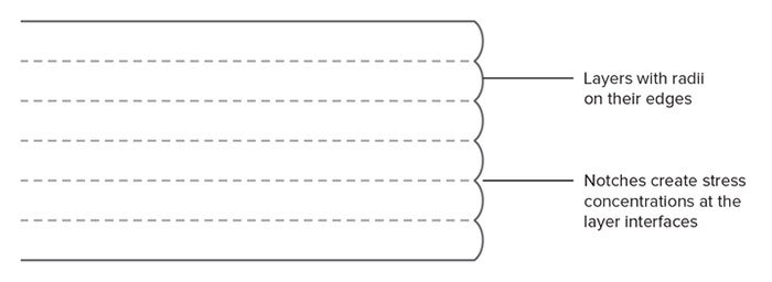
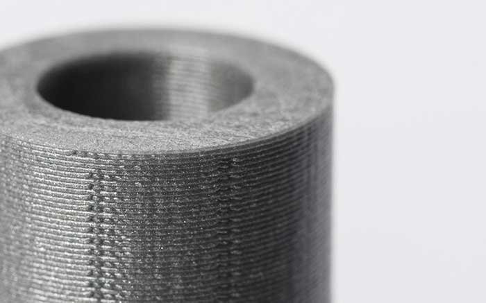
Furthermore, since the molten material is compressed onto the previous layer, its shape deforms into an ellipse. This means that FDM parts will always have a wavy surface, even for low layer heights, and small features such as holes or small grooves may need to be reprocessed after printing.
Support Structure in FDM 3D Printing
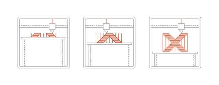
Support structures are necessary for creating overhanging geometries in FDM. Melted thermoplastic cannot be deposited into thin air. Therefore, some geometries require support structures. A detailed article explaining the use of support structures can be found here.
Surfaces printed on support generally have lower surface quality compared to the rest of the parts. For this reason, it is recommended to design the part in a way that minimizes the need for support.
Supports are usually printed with the same material as the part. There are also soluble support materials, but they are mainly used in high-grade desktop or industrial FDM 3D printers. Printing on soluble supports significantly improves the surface quality of the part but increases the overall printing cost, as specialized machines (with dual extrusion) and the relatively high cost of soluble materials are required.
Infill and Shell Thickness in FDM 3D Printing
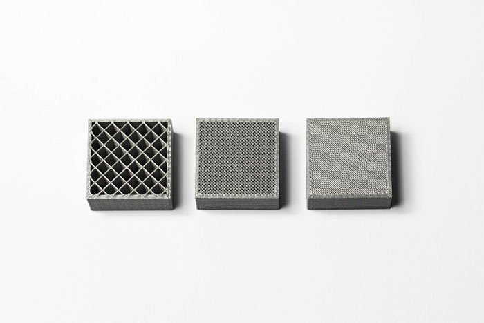
FDM parts are typically not printed solid (completely filled) to reduce printing time and save materials. Instead, the outer perimeter is printed using several passes, called the shell, and the internal space is filled with a low-density internal structure, called infill.
Infill and shell thickness greatly influence the strength of a part. For desktop FDM printers, the default setting is 25% infill density and 1 millimeter shell thickness, which provides a good balance between strength and speed for quick printing.
Latest Articles in your inbox
Subscribe to our newsletter to get the newest manufacturing and industrial services articles in your inbox once a week.

