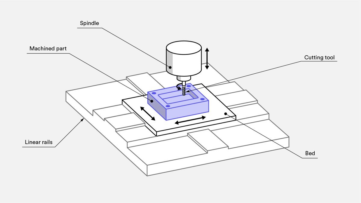
Different Parts of a CNC Milling Machine
CNC machines, regardless of their type, consist of common components. A CNC machine is made up of three main parts: mechanical, control, and power. Each of these parts includes various components, which we will get to know more about. Below, you can see the parts related to each section of the CNC machine. We will introduce the components related to the mechanical part of the machine.
Machine Body or Chassis
The body or chassis of the machine is one of the important parts of a CNC machine. All other parts like rails and carriages, motors, ball screws, rack, pinion, etc., are mounted on the machine body. The chassis can be made of cast iron or steel. Comparing steel and cast iron bodies, steel bodies are cheaper to produce, while cast iron bodies, due to their special structure, have a greater ability to absorb the vibrations of the machine.
Machine Motors
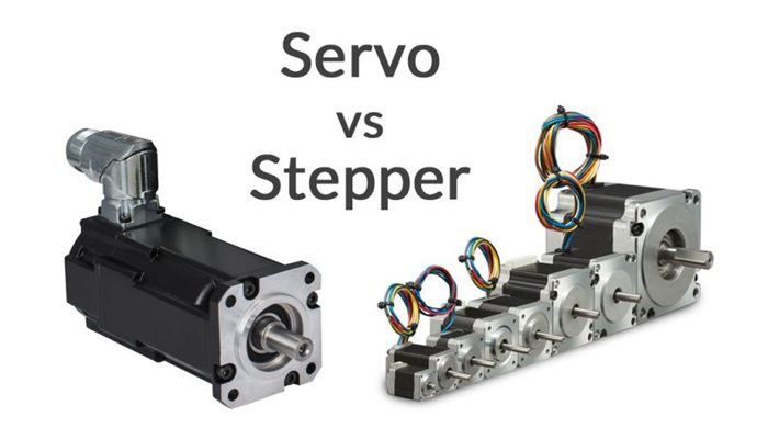
CNC machines use two types of motion motors: servo motors and stepper motors.
A servo motor is an electric motor designed for use in a feedback control system. Feedback is an important concept in CNC machines. Instructions are transmitted to the components one after another, and the components act according to these instructions. Now, imagine if one of these instructions is not executed correctly and the movement associated with that instruction does not occur. If the next command is executed while one of the previous commands has not been completed, all subsequent component movements will likely be affected by the unexecuted command, resulting in unsatisfactory machine performance. To prevent such situations, feedback systems are used.
Feedback systems are designed to monitor the correct execution of a command after it is sent and only issue the next command after ensuring the correct execution of the previous one. In essence, a feedback system creates a two-way communication between the CNC machine’s computer and its components, reducing the likelihood of errors in the process. One of the advantages of servo motors is that they have low inertia, allowing them to quickly execute successive start and stop movement commands.
A stepper motor or step motor is another motor used in CNC machines. A stepper motor divides a 360-degree rotational movement into several small movements of equal size. For example, a 200-step stepper motor rotates 1.8 degrees in each step. Stepper motors operate without the use of feedback systems. Stepper motors are brushless and thus when pulses are applied to their terminals, the shaft position rotates a predetermined amount, while DC brush motors continue to rotate continuously as long as voltage is applied to their terminals and do not have step-by-step movement.
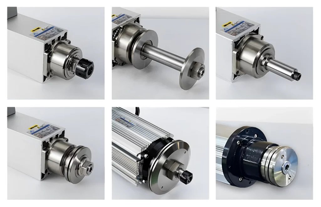
Spindle
The spindle is an electric motor responsible for creating high-speed rotational movement and holding the cutting tool. Spindle motors heat up quickly due to the generation of high-speed rotational movement. Two types of cooling systems are used to reduce the temperature of these electromotors: air-cooled and water-cooled. Water-cooled spindles are more efficient in cooling, although they require more careful maintenance.
The speed of these electric motors can be adjusted using an inverter. The inverter controls the speed of the spindle by increasing or decreasing the frequency received by the spindle. Spindles are categorized into two types based on tool exchange: tool change spindles and manual spindles. In the tool change type, the tool exchange process is automatic, thus saving time.
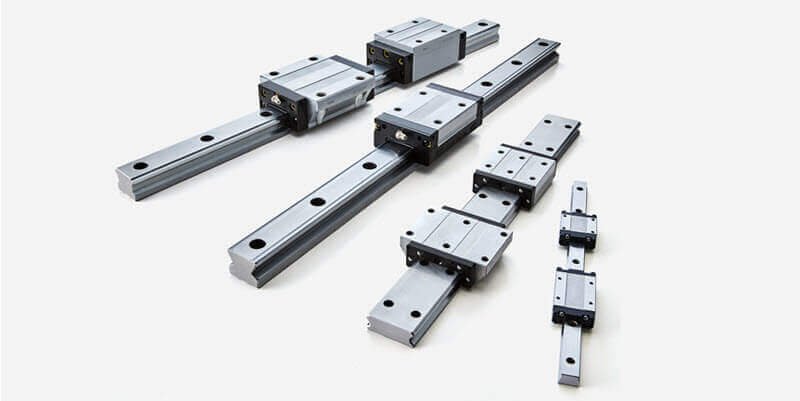
Rail and Carriage (Linear Guide)
Linear reciprocating movement is one of the most repeated movements in a CNC machine. Rails and carriages (linear guides) are used to create this movement. A linear guide is an important motion mechanism that supports mechanical loads for guidance in linear motion paths with minimal friction. It is important to note that the rails must be placed on a completely flat and smooth surface; otherwise, rapid wear of the rail and carriage will occur.
CNC Machine Motion System
Motors create rotational movement. The conversion of rotational movement to linear movement is the responsibility of components in the machine’s motion system, including ball screws, timing belts, rack and pinion, and gears.
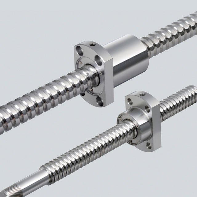
Ball Screw
The ball screw in a CNC machine is used to convert rotational movement into linear movement and to smooth the movement of the nuts with minimal backlash and friction. The presence of backlash and friction between the nuts in a CNC machine can adversely affect its performance. The structure of a ball screw consists of three main parts: the screw, the nut, and the balls. The movement of the screw and nut alongside each other leads to friction and, consequently, deviation in movement. To compensate for this shortcoming, a large number of balls are placed between the screw and the nut. The movement of these balls between the screw and the nut minimizes friction, thereby allowing for precise movements.
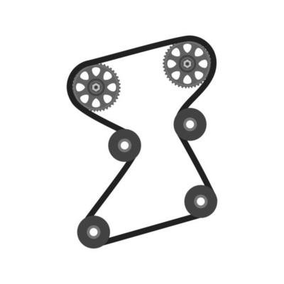
Timing Belt
Another method of converting rotational movement into linear movement in a CNC machine is the use of a timing belt. A timing belt is made from a combination of flexible polymeric materials with inelastic fibers for transferring power from one pulley to another. Timing belts are suitable for lightweight and non-load-bearing devices such as printers and laser machines. However, there is a significant drawback to using timing belts in machines: over long paths and after a period of use, the rubber of the belt can stretch, leading to a reduction in the overall accuracy of the system.
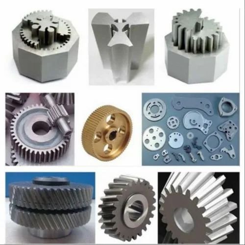
Rack and Pinion
The use of gears is another way to convert rotational movement into linear movement in CNC machines. For CNC wood and MDF machines, the best option is to use a rack and pinion system because it is less sensitive to dust and debris. Woodworking workshops generate a lot of dust and chips during cutting and shaping wood, and this can affect the performance and lifespan of the machinery. Therefore, to increase the durability of CNC wood and MDF machines, employing a rack and pinion system is the most suitable choice. This system is more resistant to the dust and debris typically found in woodworking environments.

Latest Articles in your inbox
Subscribe to our newsletter to get the newest manufacturing and industrial services articles in your inbox once a week.